Centrifugal Clutch Optimization
MAE 413 (Design of Mechanical Systems) final project.

The Project
This was my team’s final project for the Design of Mechanical Systems class at NC State University (NCSU) taught by Dr. Eischen. The class is an overview of the theory behind mechanical elements–bolts, welds, gears, belt drives, etc.–paired with 3 team design projects that apply the theory learned.
The final project was as follows:
Determine the principal dimensions (primarily the shoes and springs) of a centrifugal clutch of the type described in US Patent 5,560,465. The clutch is to be placed between a load and a 5-hp 1750-rpm induction motor, to give initial engagement when the motor speed is 1200 rpm and complete engagement (no further slipping) at 1450 rpm and a torque of 225lb-in. The clutch should be as compact as possible.
The referenced patent can be viewed here [1]. A significant portion of our time was spent parsing and analyzing the patent’s theory, as there were several typos and ambiguities as to how the authors derived their equations and torque capacity curves.
Centrifugal Clutches
Centrifugal clutches are often found in equipment or machinery in which it is desirable to only transmit rotational power to a given load above a certain operating RPM. Some classic examples are chainsaws, go-carts, or small motorized scooters.
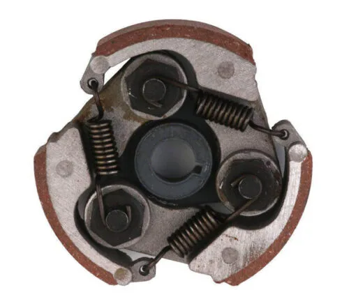
A typical example of a centrifugal clutch is shown in Figure 2. The main components are the drum (which is not shown in Figure 2, but would surround the assembly shown), shoes and associated springs, and the input shaft. When the RPM of the input shaft is high enough, the centrifugal force acting on the shoes overcomes the spring forces holding them to the input shaft, throwing them away from the center of the clutch until they contact the inside of the drum. The friction between the two surfaces then transmit the power of the input shaft to the drum / load. The shoes are kinematically restricted by pivot points, and by shoe springs with a spring rate chosen based on the desired engagement RPM.
High and Low Gain Clutch
The clutch presented in the patent is proposed to solve a few shortcomings of prior designs, including failure of the shoe springs due to the high stress within the hooks connecting them to the shoes, and catastrophic failure if the drum breaks, which would fling the shoes outward. These concerns are mainly addressed by the interlocking design of the shoes–the shoe springs (highlighted green in Figure 3) used are flat and ground compression springs rather than tension springs with hooks, and if the drum fails, the shoes are held together by the interlocked members (highlighted red).

However, the main concern the patent addresses is that prior designs do not have a smooth transition during initial engagement of the shoes. This is solved by the wedge members and associated compression springs (highlighted orange) that split the operation of the clutch into Low Gain / Threshold Gain mode and a High Gain mode:
-
In the low-gain region, the shoes have have been thrown outward to begin making contact with the drum, but the wedge members are held against the dogs (highlighted blue) of the input shaft by the wedge springs. The operating RPM of this region starts at $\bf{S_o}$.
-
As RPM increases, the threshold gain region beings as the wedge members being to move radially outward, compressing the wedge springs. This region begins at RPM $\bf{S_1}$.
-
During both the low-gain and threshold-gain modes, the shoes are engaged to the inside of the drum, but slip has not been eliminated.
-
If the RPM continues to increase, the clutch enters the high-gain region as the wedges fully contact the end of their drive slots. The RPM this transition occurs is $\bf{S_2}$.
High and low-gain curves provided in the patent’s analysis can be seen in Figure 4. In actual operation during threshold-gain mode, the torque transmitted would transition from the low-gain to the high-gain curve, with full engagement occurring at the intersection of the high-gain curve with the vertical dotted line represent $S_2$.


In other words, the centrifugal force on the wedge members at $\bf{S_2}$ is equal to the compressive force on the wedge springs. Once this occurs, the radial contribution of the normal force $F_N$ between the wedge and the associated dog of the input shaft, $F_{Y2}$, begins contributing to the total outward force acting on the shoe. A diagram for low-gain forces associated with the wedge can be seen in Figure 5, and can be compared with the high-gain forces seen in Figure 6.
Torque Capacity
Using Matlab, We modeled the clutch using the governing equations presented in the patent. The low gain curve equation is as follows:
\[T_{CL} = n(F_{GS}-F_{SR}-F_{Y1})\mu R_D\]Where $n$ is the number of shoes, $F_{GS}$ is the centrifugal force acting on one shoe, $F_{SR}$ is the total spring force from the shoe springs, $\mu$ is the coefficient of friction of the inner drum lining / shoe interface, and $R_D$ is the radius of the drum.
Because centrifugal force is proportional to the square of rotational speed, and $F_{SR}$ is defined to be equal to $F_GS$ at $N=S_o$, the low-gain curve is then:
\[T_{CL} = n(F_{GS}(N^2-S_o^2)-F_{Y1})\mu R_D\]The high-gain curve equation is:
\[T_{CH} = n(F_{GS}+F_{GW}-F_{SR}-F_{Y2}) \mu R_D\]or:
\[T_{CH} = n(F_{GS}(N^2-S_o^2)+F_{GW}-F_{Y2}) \mu R_D\]Where $F_{GW}$ is the centrifugal force on the wedge. Similar to the high gain equation, $F_{GW}$ is equal to the force on on the wedge from the wedge spring, $F_{SW}$, at $N=S_2$. The relationships between spring forces and target RPMs as well as total displacement of the shoes and wedges (measured within CAD) can then be used to calculate the required rates for the wedge and shoe springs.
Motor Properties
Both $F_{Y1}$ and $F_{Y2}$ are dependent on the torque capacity of the engine $T_E$, and the actual torque transmitted by the clutch, $T_C$. Real engine and / or motor torques are determined by their own torque curves. We determined that the authors linearized the low-gain curve by setting this term equal to the average torque that was available from their power source, a 40 BHP diesel engine.
Our case is different in that we are sizing our clutch for an induction motor. Given that our motor is rated at 1750-rpm, the low-gain curve would be operating in an RPM range that would be within the pull-up torque region of an induction motor curve (see this document for further details). We therefore applied a pull-up torque factor of $1.3$ to the rated torque of our motor (15 ft-lbs).
In the high-gain region, we determined that $T_{CH}$ was set equal to the $T_C$ term within $F_{Y2}$ and solved for.
Optimization
For optimization, we focused treating the overall diameter and width of the drum as our primary parameters, and derived all other geometry from a parameterized CAD model. Detailed dimensions were not given in the patent other than overall diameter of the drum, so the closest way to derive the other geometry was to overlay the schematic provided in the patent over a the sketch plane within SolidWorks. This model was shown at the top of page in Figure 1, and a portion of the data sheet is shown below.
With this data, we could then iterate over torque capacity curves for different drum radii and width. Radius was iterated first (Figure 7) since it has a more significant affect on the overall torque capacity. Once the radius with the closest desired performance was selected, width was then iterated, keeping our selected radius of 4.25 inches constant (Figure 8). Our final curves can be seen in Figure 9 for a drum radius of 4.25 inches and a width of 1.234 inches.


Springs
From our now finalized design, we could determine our spring displacements, forces, and preloads, seen in Table 2. Final spring specifications can be seen in Table 3.
References
[1] H. A. Zindler, “Centrifugal clutch,” U.S. Patent 5,560,465, Oct. 1, 1996.
[2] “Motorcycle Clutch Care: Maintenance Tips for Beginners,” Fodsports Blog. [Online]. Available: https://www.fodsports.com/blog/motorcycle-clutch-care-maintenance-tips/. [Accessed: Jun. 24, 2026].